TDM Models
 Electric Powered R/C Aircraft plans
We accept payments and ship all countries. Plans are delivered as PDF files 1:1 scale |
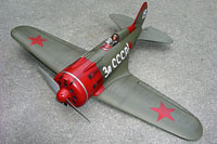
| Polikarpov I-16 "Rata" For AXI 2212/20 brushless | ||||||
 |
| |||||
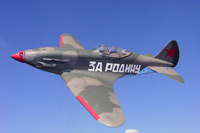
| Mikoyan-Gurevich Mig-3 For AXI 2212/20 brushless | ||||||
 |
|
|||||
| Ilyushin Il-2M Sturmovik For AXI 2212/20 brushless | ||||||
 |
|
|||||
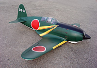
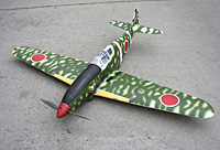
| Mitsubishi J2M3 Raiden For AXI 2212/20 brushless | ||||||
 |
|
|||||
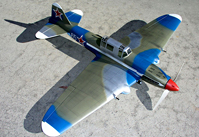
| Kawasaki KI-61 For AXI 2212/20 brushless | ||||||
 |
|
|||||
| Messerschmitt BF109F2 For Mega 16/15 brushless | ||||||
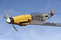 |
|
|||||
| Catapult Launcher Portable launch system | ||||||
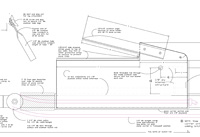 |
|
|||||
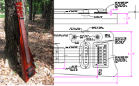
| Flat Top Mandolin Plans | ||||||
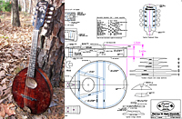 |
|
|||||
| Stick Dulcimer Plans | ||||||
 |
|
|||||
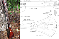
| Lap Steel Guitar Plans | ||||||
 |
|
|||||
Order ID 1114310714202548
TDM Models Home
TDM Models Home