 |
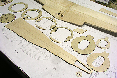
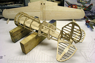
The fuselage components laid out ready for assembly. The fuselage jig is a piece of
1/8" thick balsa indented to fit notches in the formers. The jig is marked for each former location. |
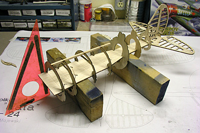 |
| After sliding the formers onto the jig, F1 is aligned to be vertical to the
jig and building table and the top center 3/16" square string is glued in place. |
 |
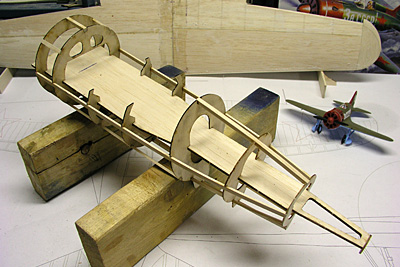
| Additional 3/32"x 3/16" stringer are added along the sides while aligning the
formers to the jig. F5, the former creating the back of the cockpit and turtle deck is angled
at 11 degrees using an angle guage. |
 |
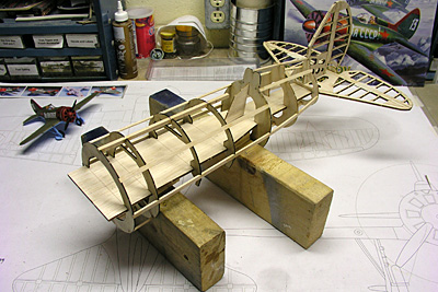
| Here is a 3/4 rear view showing the stringers aft of the former F5. The horizontal
stabilizer actually bears on the fuselage fuselage jig between F7 and the tiny round tail former
F8. The fuselage jig will be cut just ahead of F7 (the last turtle deck former) and pulled out
of the fuselage once the top half sheeting is in place. |
 |
| The last photo shows the fuselage frame turned upside down. The 1/16" balsa sides
will form the wing saddle and a 1/16" doubler will be added for additional strenth. At this
point the initial fuselage frame is assembled and it's time to start adding the sheeting. |
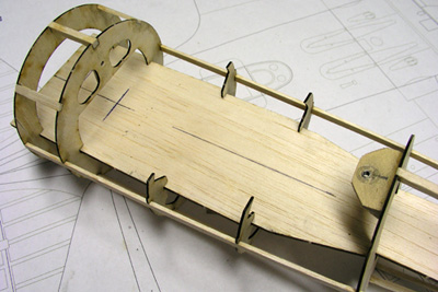 |
| At this point I decided to mount the wing to the fuselage structure to aid in
fitting the lower 1/16" fuselage sheeting (which forms the wing saddle). The wing actually
bears on the bottoms of formers F3 and F4. A 1/8" hole has been drilled in F2 to recieve the
wing dowel and a plywood plate with a blind nut will hold the trailing edge of the wing in
place. |